Logo
11/01/2026
View Tools 1.0
What is View Tools?
View Tools is a 3d studio max utility that uses some properties of the viewports to achieve modelling or visualization tasks.
The main task of View Tools is to help 3d studio max users to create 3d models starting from photographs and cameras created with Camera Match.
User's Guide
Utilities > More > View Tools
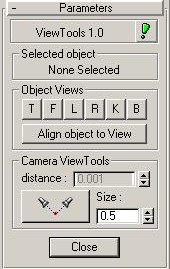
Selected Object
View Tools works only with the selected objects.
Object Views
T - F - L - R - K - B:
This buttons change the view to the object's side you choose.
This option creates a Grid Helper object named ViewToolsGrid if it doesn't exist, aligns the grid and the viewport to the object in the side you specify, and activates the grid as the valid construction plane.
Align object to view:
This option rotates the object to align its Z axis with the viewport's Z axis.
Note: This option resets the scaling of the object.
Camera View Tools
This are by far the most useful tools in this plugin. This tools camera properties like camera position-rotation-scale and FOV to move and position objects.
These tools work only with Camera viewports.
Distance:
This spinner moves the selected object far or away from the camera in the same camera line.
To make it work, open the View Tools panel, select the object you want to move, and play with the spinner.
This spinner does not auto update, so, if you move the object by hand, you will have to reselect the object to update the spinner.
Create point from 2 camera views
This tool create a little object (A Sphere with 4 segments) in a point constructed by two camera X,Y points.
To make it work, Click the button, go to Camera01 viewport and pick in it, go to Camera02 viewport and pick in it.
Note: You have to pick in two different camera viewports, and the cameras must have a different Position-Rotation and target, they can't be paralell cameras.
Tutorial:
Modelling an Old Shoe with Camera View Tools
This tutorial will show the first steps in modelling an old shoe from 5 photographs of an Old Shoe and a LEGO box (that will be used as a reference box for Camera Match).
Open the file ReferenceBox.max.
This file has only one object. A box with a set of little rectangles and squares. This box was modelled using the same dimensions of a LEGO box I build. I choosed a LEGO box because LEGO is maybe the cheapest things that has good accurate dimensions and is customizable enough to build a lot of points for a good camera matching.
Save this file as OldShoe.max
Creating the cameras from the photographs.
This process is done with Camera Match... The process won't be described in detail here, but if you need help with this step go to the 3d studio max reference guide and take a look to the Camera Matching documentation.
However, if you are lazy to do this step (which I really recommend to do)... you can open the scene ViewToolsShoe.max.
- Set the Renderign size to 640 × 480. (The photographs size).
- Activate the Perspective Viewport, go to Views > Viewport Background.
Set the file to shoe_top.bmp.
Set the Aspect Ratio to Match Bitmap.
- Rotate the viewport to roughly align the Reference Box with the LEGO box
in the photograph. Pay special atention to the details in the box, like the
blue and red rectangle marks in the base of the box, and the different squares
in the top of the box.
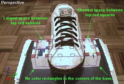
- Activate another viewport and repeat the same Viewport Background steps but for
image shoe_right.bmp
- Rotate the viewport to align the Reference Box with the LEGO box.
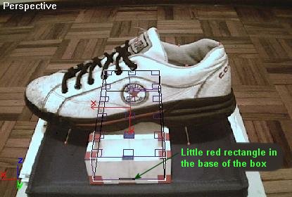
- Now, create the cameras using camera match.
For the right_shoe.bmp image, create the 6 camera points in the positions shown by the red arrows. Use 3D Vertex Snap to make sure that the points are placed in over the box.
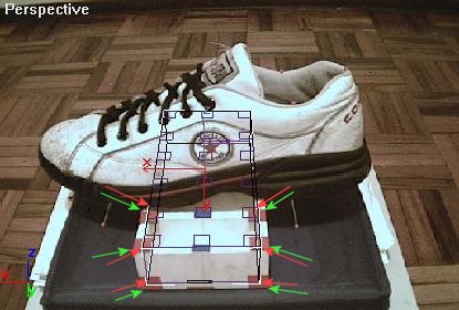
In the Camera Match panel reference these 6 points, each with its couple in shown by the green arrows, and when done click the Create Camera button. Rename this camera as Camera_Right.
For the top_shoe.bmp, create 5 or 6 camera points. Choose the ones you like the most, but remember that camera match works better with points distributed all over the box, not only in its corners, and sometimes, the more points you place, the more accurate your camera will be.
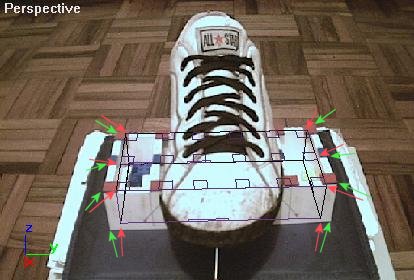
In the Camera Match panel reference these points, each with its couple in shown by the green arrows, and when done click the Create Camera button. Rename this camera as Camera_Top.
- Hide everything.
- Go to the View Tools panel and set the size of the point to 0.5.
- Click the Create Point from 2 Camera Views, and click a detail, maybe the
sew in the right side of the shoe, in the Camera_Top viewport.
- Click the same detail but in the Camera_Right viewport.
A new point is created in the sew, or very near to it, dependending on the camera error.
Camera Error: The process of creating a camera from a photograph is not an easy task, it involves a lot of steps, and each step adds a little error to the proces:
- The LEGO box is not a very accurate model, some of its dimensions can be a little bigger or shorter in one side of the box than in the other.
- The Reference Box object was modelled using a house ruller with a milimeters accuracy.
- The digital camera added a lot of compression to the photograph. This makes it hard to pick the exact corner point.
- 3d studio max viewport size is not the same as the photograph size, here a little distortion of the picture and the 2D antialiasing makes also hard to pick the exact point.
- The Camera Match process iterates various times until it finds the best camera, but this process is not an exact mathematical process, and a level of error is always returned in the Current Camera Error. Most of the times, this error is just the result of the above errors.
- Besides all this, when you create the point using View Tools, you are picking in a little viewport, this adds even more error to the process.
So, the chances that the point is created in the exact place you picked are very low... However, it will be created very very near, and you can place it by hand with the move tool in one viewport, and move it with Camera Distance to make it match the other viewport.
- Select the point that was created, and usint the Move Tool, move it in the
Camera_Right viewport to the seam you picked.
- Reselect the object to uptdate the Camera Distance spinner, and adjust the
value. While you adjust the value, you will see how the point moves in the Camera_Top
viewport, but stays in the same position in the Camera_Right viewport.
Make it match the sew in the Camera_Top viewport.
- Create the other 3 points needed to do the all the sews.
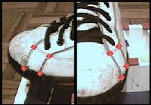
- Create a closed spline using the 4 points. Turn on Pivot in Grid and
Snap Settings.
- Finally, apply a Surface modifier to the spline you just created.
These are the basic steps to create a 3d model from a set of photographs using View Tools. Now you just have to create enough points on the shoe and connect them using a spline. Attach all the splines in a single Editable Spline object and apply a Surface modifier to it.
When you have the top-right parts of the shoe ready, load shoe_bkrt.bmp as a new viewport background, create its camera and create the back-right parts of the shoe.
Continue loading the other viewport backgrounds and creating the cameras to finish the shoe.
Here is a list of the cameras and viewport backgrounds to create them:
| Camera_top | : | shoe_top.bmp |
| Camera_left | : | shoe_left.bmp |
| Camera_bklf | : | shoe_bklf.bmp |
| Camera_back | : | shoe_back.bmp |
| Camera_bkrt | : | shoe_bkrt.bmp |
| Camera_right | : | shoe_right.bmp |
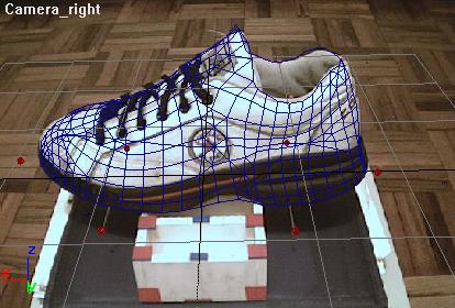
The finished shoe!